
The Care and Feeding of a Carrier Rope System
The carrier rope system was introduced over 50 years ago as an answer to the safety and time concerns of threading the paper machine by hand. As machine speeds increased, the need for a faster, more efficient, and safe method of threading was needed; therefore, the “Sheehan” carrier rope system was developed. By DeWitt T. Oliver, General Manager, Carrier Rope and Development, William Kenyon & Sons, Inc. As an integral part of the paper making operation, the carrier rope system must be maintained as a single piece of equipment, not as individual sheaves and stretchers. Just as the press section equipment and wire table require periodic maintenance, so does the carrier rope system. Lack of maintenance to the carrier rope system will show itself in numerous ways – short rope life and downtime ($$$$$) as a result of premature rope failures and poor threading being the most common. Typically the carrier rope system is overlooked until it is needed to thread the machine. At this point, it is too late to make adjustments to address the typical problem areas such as the pickup nip and transfer and release points. This is, however, the best time to do a complete system survey to assess the threading process. A determination can then be made as to what areas require immediate attention and what can be modified on an ongoing basis as a part of a continuous system improvement program. CARRIER ROPE SELECTION Carrier rope selection is typically made by the operators or superintendent and is usually based somewhat on machine conditions but mostly on the machine history. Several factors should be considered when choosing a carrier rope: Machine speed. This is not the most important issue, however, it does enter the equation. Higher machine speeds require a close speed match between the ropes and sheet to ensure an efficient tail carry with little or no slack. Rope diameter will, in some positions, have an affect on rope speed. 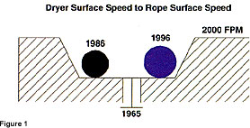 Dryer groove. The dryer groove depth is the major factor in determining carrier rope diameter and style. Typically older machines have a rope groove that can range anywhere from 1/2″ to 1″ deep and 1 1/2″ to 2″ wide. Use of a small-diameter rope in these cans will affect threading, as the rope speed will be considerably lower than the dryer surface. In addition, due to the groove width, small diameter ropes may separate in the groove, as they will not be contained by the rope groove sidewalls. On a machine running at 2000 FPM with 60″ cans and a 5/8″ deep rope groove, there will be a speed difference of approximately 35 FPM between the rope groove surface and dryer can surface. The surface of a 3/8″ three-strand (or twisted) rope will run at approximately 1986 FPM and a 1/2″ rope at 1996 FPM (both under tension). (See Figure 1) Three-strand rope, because it is solid, will maintain its diameter and fill the groove in both width and depth, keeping the ropes tight together and tall in the groove. Some newer dryer cans have shallow rope grooves, 1/2″ to 3/8″, that are designed to use small-diameter three-strand or braid without a core. Position. The machine position, dryer section, size press, coater, etc., also come into play in choosing a carrier rope. Whether a coated or uncoated rope is needed, three-strand or braid, braid with a core or without, is determined by the position and the demands put on the carrier rope. Typically an uncoated three-strand rope will be used in the dryer sections while the size press and coater sections will use a coated, or treated, braid or three-strand, to combat the effects of size and/or coating and wash-up chemicals. EQUIPMENT Although there are several different materials used to manufacture carrier rope sheaves, the best for the most applications is cast iron. Bearing-grade nylon, polyethylene, aluminum, brass and stainless steel are a few other materials that have been, and still are, used with limited success. Aluminum, brass, nylon, and polyethylene are soft materials and will eventually develop secondary grooves as a result of normal wear, high rope tension, and stalls caused by failed bearings or paper wads. Stainless steel is typically used in positions that are subjected to frequent wash-ups and chemical cleaning. Cost is the major limiting factor with stainless steel. Mounting hardware is an important part of the rope system and is the single link to maintaining proper alignment for threading. It is also important in securing the sheaves during a rope failure because of wads and/or broke in the system. Mounting hardware should be constructed of solid steel and offer a means of securing the final mounting position through a combination of lock bolts with jam nuts and predrilled taper pin pilot holes. Commonly referred to as “rope stretchers” the carrier rope tensioning equipment has a critical role in a reliable, efficient threading system. The main purpose is to tension the carrier ropes to maintain a tight nip on the tail and keep the ropes together through the run. Stretching the ropes will lead to premature failures, as their natural elasticity is reduced, as well as their ability to recover from wads and irregularities in the system. This is the exception to the age-old papermakers’ rule of “if a little is good, more is better, and a lot is perfect.” A properly operating rope tensioner will work with the ropes to keep them tight but not allow them to stretch as a result of wads passing through the system. The slider carriage(s) in a tensioner that is operating properly will move to adjust for wads caught in the ropes, normal elongation, and shrinkage of the ropes as a result of the combination of wear, moisture, and heat. The tensioners should be set to give a minimum of 55, and a maximum of 75, pounds of rope tension during threading to ensure a tight nip between the ropes – the lower end of the scale being for lightweight paper and the higher end for heavyweight and coated board. On a pneumatic system, the air pressure setting to achieve this will be determined by the cylinder diameter and tensioner type. On a weighted unit, rope tension will be a function of the amount of weight hanging on the cables and the tensioner design. The OEM should be contacted to determine the proper settings. The tensioner controls, if automatic, should allow a dual tension setting, HIGH for threading (as noted above) and LOW for normal running. The low-tension setting will allow the ropes to recover from the higher tension, maintaining their natural elasticity. It will also minimize wear on the ropes by reducing the effects of abrasion. High tension will negatively affect threading by reducing the diameter of the ropes, which may result in the ropes separating in the open draws. Periodic maintenance of the tensioners should be performed on every down. On pneumatic systems, this should include the following:
- filling the oil mister cups
- cycling the cylinders without the ropes on
- cleaning the slide rails/pipes to remove paper dust, excess grease, and paper wads
- a visual check of the cables and cable sheave condition (if equipped)
- greasing all of the sheave and wheel bearings, etc.
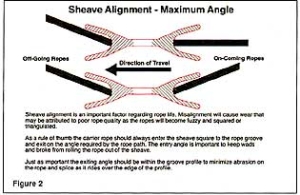
On weighted units, the slide rails, cables, and cable sheaves should be cleaned and lubricated and the actual tension checked to be sure the correct amount of weight is hanging on the cable. SYSTEM SETUP AND ALIGNMENT Aside from proper tension, alignment is the most important aspect of an efficient system. System alignment is not limited to the position of the ropes at the nip or through the system itself. Alignment includes positioning the pick-up nip in a location that is user friendly and does not require the operator to feed the tail blindly or by positioning him or herself in an unsafe area or stance. The nip should be positioned so the operator is able to make a single motion from the previous release to the new nip, a maximum of 4 to 5 feet. Any further than this and an air or belt system should be considered. Due to circumstances on the machine, it is not always possible to follow recommended alignment principles. New equipment to improve or simplify the papermaking process is taking what little space is available on the machine. Typically the carrier rope system is the last piece of equipment considered when making modifications to the machine. It is also the first thing to be moved and/or modified to install new equipment such as blow boxes, scanners, etc. Therefore, threading may be compromised, requiring the system to be re-engineered to restore threading efficiency. In general, sheaves should be set so the ropes enter straight and exit on an angle if needed. The exit angle should never be greater than the sheave side wall angle so the rope does not run on the edge of the sheave. (See Figure 2) The use of adjustable hardware in these positions will simplify and improve alignment.
 The following should be used as a rule of thumb to determine sheave size when setting up or re-aligning the system. This is based on 2000FPM and should be adjusted for faster (increase sheave diameter) or slower (decrease sheave diameter) machines. At the noted speed a 6″ sheave should have a maximum of 45° of wrap, an 8″ 90°, a 12″ 120° and a 14″ 180°. Following this guideline will minimize the effects of internal rope wear due to fiber flexing and abrasion. MAINTENANCE Maintenance of the system should not be limited to a weekly or monthly walk-through by an oiler when the system is down. The condition of the bearings, rope surface, mounting hardware, and alignment should also be checked during the down and when the machine is up and running. This is the only way to assess the condition of the threading system and not just the individual pieces of equipment. Sheave condition is critical to rope life and will cause down time if it is not monitored. Secondary grooves (See Figure 3)will shorten the life of the rope by cutting the rope fibers in both the splice and the body of the rope itself. This is typical with aluminum, brass, and nylon sheave materials and is the result of wear caused by overtension and sheaves stalled by either frozen bearings or wads in the system.
 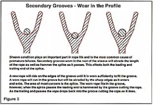 Housekeeping is also a major part of daily maintenance. Just as the machine floor equipment must be cleaned to facilitate threading and minimize the potential for paper breaks, so should the return runs of the carrier rope system. Accumulations of broke and wads in the system will affect rope life, especially if they are jammed in, or around, the rope stretchers and sheaves. The potential for a new sheet break during, or just after threading, is increased if broke is allowed to accumulate around the system equipment and is pulled into the threading path by the ropes. CONCLUSION The carrier rope system must be looked at as a complete system and maintained that way. The proper equipment for the application, correct alignment, nip and release arrangement, and carrier rope type must be used to ensure an efficient, reliable, and repeatable tail threading operation. Attention to details such as housekeeping, proper rope tension, and alignment at the nip points and through the system in general is critical in maintaining an efficient system. Carrier rope selection is a factor also and should be based on the previously noted points. If all points are considered and addressed, the carrier rope system should perform as intended – to thread the tail through the machine with little or no operator’s assistance, minimal slack in the tail and at full machine speed for the particular paper grade.